Berkeley Out-of-Order Machine (BOOM) v4 设计说明

总体概述

BOOM(Berkeley Out-of-Order Machine)是加州大学伯克利分校开发的开源高性能乱序执行RISC-V处理器内核,支持RV64GC指令集docs.boom-core.org。BOOM采用了**统一物理寄存器文件(PRF)**的设计,即通过显式重命名将架构寄存器映射到比架构寄存器数更多的物理寄存器上,实现对写后写(WAW)和写后读(WAR)相关的消除docs.boom-core.orgdocs.boom-core.org。这种设计与MIPS R10000和Alpha 21264等经典乱序处理器相似docs.boom-core.org。BOOM通过Chisel硬件构造语言编写,具有高度参数化特性,可以视作一系列同族微架构而非单一配置。

在微架构上,BOOM的流水线概念上可分为10个阶段:取指解码寄存器重命名派遣发射寄存器读取执行存储访问写回提交chipyard.readthedocs.io。不过实现中为了优化性能,这些阶段有合并:BOOM实际实现为7级左右的流水,如“解码/重命名”合并、“发射/寄存器读取”合并等chipyard.readthedocs.io。整个处理器可分为前端(取指及分支预测)和后端(乱序执行核心,包括重命名、调度、执行、提交)两大部分,它们通过取指缓存和队列衔接。

BOOM集成在Rocket Chip SoC框架中,复用Rocket的许多组件(如L1缓存、TLB、页表遍历单元等)docs.boom-core.org。下面将按模块详细说明BOOM v4的设计,包括各模块功能、关键数据结构和类、模块间交互以及完整的指令流水流程。

前端:取指与分支预测

BOOM的前端负责从指令缓存取出指令,并进行分支预测以保持流水线尽可能满载。BOOM使用了自研的前端模块(BoomFrontend),Rocket Chip的Rocket前端只是提供了I-cache等基础结构docs.boom-core.org取指过程如下:

  • 指令缓存(I-Cache): BOOM复用了Rocket Core的指令缓存实现。I-Cache是一个虚地址索引、物理地址标记的集合相联缓存docs.boom-core.org。每周期前端根据当前PC从I-Cache取出一个对齐的指令块,并将其暂存,以便后续解码使用docs.boom-core.org。I-Cache命中后提供指令位串;若未命中则触发访存请求,前端将停顿等待指令返回。
  • 取指宽度与取指包(Fetch Packet): BOOM支持超标量取指。每周期前端可取出一组指令,称为一个“取指包”,其大小等于前端取指宽度(例如2或4条指令)docs.boom-core.org。取指包中除了指令本身,还包含有效位掩码(指示该包中哪些字节是有效指令,例如应对RVC压缩指令)以及基本的分支预测信息docs.boom-core.org。这些信息将用于流水线后段的分支处理。
  • Fetch Buffer: 前端包含一个取指缓冲区,暂存取出的取指包docs.boom-core.org。取指包从I-Cache出来后进入该缓冲区,以解耦取指与解码阶段。如果解码或后端暂时阻塞,取指缓冲可以暂存多个取指包,避免前端I-Cache停滞。解码阶段将从取指缓冲区提取指令。
  • Fetch Target Queue (FTQ): BOOM前端还维护一个取指目标队列(FTQ),用于跟踪流水线中各取指包对应的PC、分支预测信息等元数据docs.boom-core.org。每当前端取走一个新的取指包,就将其起始PC、末尾预测的下一个PC或分支目标等信息记录到FTQ。FTQ的存在使得当后端检测到分支预测失误、异常等需要改变控制流时,能够快速找到对应取指包并提供恢复信息(例如正确的下一PC)。FTQ有效地充当了前端和后端之间关于控制流信息的接口。

分支预测对于维持高性能至关重要。BOOM前端在取指流水线中嵌入了多级分支预测器,尽量在取指当下周期就对可能的分支做出预测,从而“抢先”更新PC,减少取错指令的浪费。BOOM的分支预测主要包括:

  • 静态BTB&BIMODAL预测: BOOM包含一个**Branch Target Buffer (BTB)*用于缓存最近遇到的分支地址及其目标,提供直接的PC跳转。配合BTB的是一个简单的*双模(Bimodal)分支预测器,使用全局历史或局部历史记录去预测分支方向(Taken/Not taken)。双模预测提供了快速但相对粗粒度的方向预测。
  • TAGE/Tournament预测: 为提高复杂分支的预测精度,BOOM还实现了更先进的TAGE(Taggeed Geometric Predictor)和/或**组合赛选(Tournament)**预测器。在v4中,ifu/bpd/包下包含多个预测器实现文件(如tage.scalatourney.scala等),表明BOOM支持可配置的分支预测组件。这些动态预测器利用多位历史模式,大幅提升分支方向预测的准确率。
  • 返回地址栈 (RAS): 对于函数调用和返回指令,BOOM使用RAS来预测返回地址。每遇到Call指令将其下一地址压栈,遇到Ret则从栈弹出预测返回PC。

通过以上机制,BOOM前端可在取指阶段多次重定向指令流:在取指流水线的每个cycle,前端使用分支预测组件判断当前取指包内是否有跳转/分支,如果有则预测其方向和目标PC;若预测为跳转且目标已知,前端会立即将PC切换到预测目标,在下一cycle从新地址取指docs.boom-core.org。这样,即使取指包中有分支,前端也不必等其实际执行就能预先沿预测路径取指,提高并行度。如果后端执行后发现某分支预测错误或有异常发生,则向前端发送Flush信号和正确PC,前端将丢弃错取的指令并从正确PC重新取指docs.boom-core.org。这种前端/后端配合保证了即使发生乱序执行,控制流也能快速恢复。

前端关键的类/模块包括:BoomFrontend(作为LazyModule封装前端总体),其内部BoomFrontendModule连接I-Cache(封装自Rocket的ICache类)、指令TLB、FetchBufferFetchTargetQueue以及分支预测流水线等组件。分支预测部分在源码中由诸如BimodalTagePredictorRAS等类实现,并由BoomBPredictor(见predictor.scala)统一管理。通过参数配置,不同级别的预测器可组合启用,实现性能与硬件成本的折中。

)

解码阶段从前端取指缓冲区获取取指包,对每条指令进行译码,将其翻译成微操作(Micro-Op, uop)并做初步的资源分配检查docs.boom-core.org。BOOM的解码器支持RISC-V标准的RV64GC指令,包括整数、乘除、原子、浮点、CSR等各类操作。其主要功能和流程:

  • 指令译码: 解码器将每条取出的指令位模式译码成内部控制信号(如操作码、源目标寄存器编号、立即数等),生成BOOM内部使用的MicroOp对象。在BOOM源码decode.scala中,DecodeUnit类包含详细的译码查表,将RISC-V指令映射为对应的uop控制信号。
  • 压缩指令展开: 对于16位的RISC-V压缩指令(RVC),BOOM利用Rocket提供的RVCExpander对其进行展开docs.boom-core.org。展开后的指令在微架构上等效为对应的32位非压缩指令。这样,后续流水线不需特意处理压缩指令,简化了实现。
  • 微操作拆分: 某些复杂指令在BOOM中会拆分为多个微操作。例如,RISC-V存储指令会拆成“计算地址”的STA uop和“提供数据”的STD uop(详见LSU部分),AMO原子指令也会拆解成加载、计算和存储多个uop。Decode阶段负责根据指令类型产生适当数量的MicroOps并标记它们的关系(如STA/STD属于同一Store指令)。
  • 资源分配检查: 为保证后续流水线有空间容纳新指令,Decode阶段会检查关键共享资源是否有空闲条目,比如ROB、重命名映射表、Free List、Issue队列、Load/Store队列docs.boom-core.org。如果其中任何一个已满(即当前在飞指令过多),Decode必须停顿(stall),不再从取指缓冲读取新指令,直到资源释放。这样避免了过度发射导致后端溢出。
  • 分支谱系信息: 解码时还会处理分支相关信息,例如每条指令会带有一个分支掩码(Branch Mask),指示当前指令受哪些未决分支的影响。这在BOOM的实现中用于决定分支错预测时需要flush哪些指令。Decode阶段生成并更新这些掩码信息,供Rename阶段及ROB追踪。

实现方面,DecodeUnit(源码decode.scala)包含IO接口DecodeUnitIo(输入取指包,输出解码后的uop序列)。解码输出的每个MicroOp附带了各种控制字段,如操作类型、源/目的寄存器号、立即数、是否为分支或存储等。BOOM的decode支持每周期多发射:若取指包内含多条指令且资源允许,Decode会一次性产生多条uop并并行进入后续Rename阶段。对于RISC-V特有的Fence等内存序列化指令,Decode会特殊处理,在uop中标记并在ROB中进行顺序控制。

总之,Decode阶段将前端提供的原始指令序列转化为BOOM内部的操作序列,并确保后端资源可用,为进入乱序执行做好准备docs.boom-core.org

)

在乱序执行机器中,寄存器重命名是关键环节。BOOM采用了显式重命名(Explicit Renaming)架构,实现了一个统一的物理寄存器文件(PRF),所有的架构寄存器(包括整数和浮点寄存器)在执行前都会映射到PRF中的一个物理寄存器上docs.boom-core.org。重命名阶段的主要功能是消除假相关:通过将指令的源/目的寄存器编号换成物理编号,从而消除写后写(WAW)和写后读(WAR)冲突,仅保留真正的数据依赖(读后写,RAW)docs.boom-core.org

BOOM的重命名阶段在每周期对解码出的每条uop执行如下操作docs.boom-core.org

  • 源寄存器重命名: 对于每个源操作数(逻辑寄存器号),在**重命名映射表 (Rename Map Table)**中查找得到对应的当前物理寄存器号docs.boom-core.org。这样,uop的源操作立即被标记为指向具体的物理寄存器。对于BOOM v4而言,整数寄存器x0-x31和浮点寄存器f0-f31都有各自的映射表条目。
  • 目的寄存器重命名: 如果uop有目的寄存器(写结果),重命名逻辑从自由列表 (Free List)*中分配一个空闲的物理寄存器作为新的目的物理寄存器docs.boom-core.org。同时,在重命名映射表中将该逻辑寄存器更新为新的物理寄存器号。这样后续的指令会看到这个最新映射。在更新前,映射表中原先对应该逻辑寄存器的旧物理寄存器号即成为*“陈旧的目标”(Stale Destination)docs.boom-core.org。BOOM会将这个旧物理寄存器号暂存(通常存入ROB条目),以便等到指令提交后再释放回Free List供重复利用。
  • 分配ROB和队列条目: Rename阶段为每个uop分配一个ROB入口,以及Issue队列、Load/Store队列等所需的条目索引(这些资源已经在Decode时检查过可用)。Rename会将ROB索引、LSQ索引等附加在uop上,供后续阶段使用。
  • 设置Busy位: 对新分配的物理目的寄存器,在**繁忙表 (Busy Table)**中标记为“繁忙”docs.boom-core.org(表示尚无有效数据)。当下游执行单元计算出结果并写回时,会清除相应的繁忙位,表示物理寄存器现在包含有效值。Busy Table通过跟踪物理寄存器是否就绪,辅助Issue队列判断uop依赖是否满足。
  • 分支快照: 为了支持高效的分支误预测恢复,BOOM在Rename阶段对每条分支指令都会快照保存当前的Rename Map表和Free List状态docs.boom-core.orgdocs.boom-core.org。具体来说,每遇到一个分支,Rename Map Table当前内容会复制一份与该分支关联;Free List也会保存当前未分配物理寄存器的列表(或使用一个并行的“已分配列表”来记录此后的新分配)docs.boom-core.org。如果将来该分支发生误预测,恢复机制可以在一个时钟内将Rename Map恢复到分支时的状态,并撤销在此之后的所有物理寄存器分配。这一机制极大提高了分支恢复速度,因为无需逐条回滚指令状态。

Rename阶段高度并行:BOOM设计允许每周期对多条指令同时进行重命名,这需要多端口的映射表和Free List。硬件上,Rename Map Table通常实现为多读多写端口的寄存器阵列,Free List则可用位图或FIFO实现快速分配和回收空闲寄存器。Busy Table往往是一个位向量,长度等于物理寄存器数,其在Rename分配目的寄存器时置1,在写回阶段由执行结果的完成信号清0docs.boom-core.org

BOOM v4的实现中,rename-stage.scala定义了重命名模块的逻辑,包含Map Table (RenameMapTable类)、Free List (RenameFreeList类)和Busy Table (RenameBusyTable类)的具体实现。这些类通过组合,形成Rename阶段的主要子模块。构造参数包括物理寄存器总数、重命名宽度等。主要方法包括分配空闲寄存器、备份/恢复映射表、查询和更新忙碌状态等。通过重命名,所有进入乱序后端的uop都携带物理寄存器标识,从而后端可以完全使用物理寄存器文件进行读写,摆脱架构寄存器数目的限制docs.boom-core.org

) 与派遣阶段 (Dispatch Stage)

一旦指令经过重命名,它们将进入**派遣(Dispatch)阶段,分配到重排序缓冲区(ROB)发射队列(Issue Queue)**中。ROB是乱序处理器维护指令顺序和支持提交的重要结构。BOOM的ROB承担以下角色:

  • 跟踪乱序指令状态: ROB记录所有在飞(in-flight)指令的信息,包括它们的顺序、执行完成状态、异常状态等docs.boom-core.org。ROB的本质是一个循环缓冲区,按照程序顺序排列指令。ROB头指向最早的在飞指令,尾指向最新分派的指令docs.boom-core.org
  • 保证顺序提交: 尽管执行是乱序的,但ROB确保提交(对架构状态的更新)按程序顺序进行,以保持架构上的顺序语义docs.boom-core.org。只有当一个指令到达ROB头且标记为已完成时,才会被提交,更新其结果到架构寄存器/内存,并从ROB移出。这样对软件而言,好像指令是顺序执行的。
  • 异常和分支处理: ROB也负责处理异常和分支错预测。每个ROB项包含一位标识该指令是否产生异常docs.boom-core.org。如果ROB头的指令标记了异常(例如非法指令、存储访问错误等),处理器将在提交该指令时触发异常处理流程:ROB发出流水线flush信号,取消所有未提交的后续指令,并将PC重定向到异常处理入口docs.boom-core.org。对于分支错预测,ROB检测到错预测的提交条件时(通常通过异常标志或专门信号),也会触发前端flush并恢复Rename快照。

BOOM v4的ROB实现细节:

  • 结构和容量: ROB大小(条目数)是参数化的,例如典型配置下可能有numRobEntries=ROB_SZ。为了支持每周期同时分派和提交多条指令,BOOM采用分段(banked)ROB结构docs.boom-core.org。概念上,可视ROB为W行,每行W列的阵列(W为机器宽度,例如发射宽度)。每个周期最多可向ROB写入W条新指令(填满一行)并提交W条已完成指令(从另一行)docs.boom-core.org。这样设计简化了多指令并发操作:取指包中的W条指令占据ROB同一行的多个列,共享一个程序计数器PC(低位由列索引推断),从而减少PC存储开销docs.boom-core.org。当然,如果取指包未满W条(例如遇到分支边界),则该ROB行会有空位,但仍占据一个PC条目docs.boom-core.org
  • ROB项内容: 每个ROB条目存储的信息相对精简,包括:有效位(该entry是否有指令)、完成标志(该指令执行是否完成,即“busy”位)docs.boom-core.org、异常标志(指示是否发生异常)docs.boom-core.org、以及一些需要在提交时更新的少量状态(如分支预测是否正确、存储指令的地址或SC是否成功等)。架构目标寄存器的值一般不存储在ROB中(BOOM采用显式PRF设计,所以结果直接写物理寄存器文件)。ROB更关注指令状态而非数据值。

派遣阶段的流程是:当指令通过Rename后,立即派遣到ROB和Issue队列中docs.boom-core.org。具体而言,BOOM会为每个uop选择一个ROB空闲位置(在ROB尾),并将该uop的一些信息写入ROB条目,同时也将uop送入对应的Issue队列等待执行docs.boom-core.org。派遣操作每周期最多处理与解码/重命名宽度相同数量的uop。若ROB已满或下游Issue队列已满,派遣会暂停,从而也阻止新的指令重命名,直至有空间释放。

值得注意的是,ROB的索引在Rename时就已分配给uop,派遣阶段实际执行将uop写入ROB存储的操作。这在源码中由Rob类完成,其io.enq接口接收派遣的uops写入。ROB对外还提供io.deq用于提交时读出信息,以及异常处理接口等。

BOOM的ROB实现类为Rob(见rob.scala),其构造参数包括ROB大小、发射/提交宽度等。ROB内部通过循环索引和银行划分来管理存储。还有一个RobIo定义了ROB与外部的交互信号(如与Rename、Issue、执行单元、提交单元的接口)github.com。ROB会与执行单元和写回阶段交互,当指令执行完毕会通过完成广播通知ROB清除相应busy位。当ROB头指令busy位为0(完成)且没有等待的异常/分支,需要提交时,ROB触发提交逻辑(见后文)。

总之,ROB与Dispatch阶段一起,起到了连接乱序执行各部分的中枢作用:它记录了指令乱序执行的状态,并最终以正确顺序提交结果,使处理器对编程模型表现为顺序执行docs.boom-core.org

)

发射队列(Issue Queue)是乱序处理器中用于暂存已派遣但尚未执行的微操作的结构。BOOM的Issue单元决定何时从这些等待队列中选择指令发送给执行单元。BOOM v4在Issue单元上的设计具有以下特点:

  • 多队列拆分:BOOM采用分离的Issue队列,根据指令类型划分不同的队列docs.boom-core.org。典型地,BOOM有整数运算队列浮点运算队列访存队列三类docs.boom-core.org。整数ALU指令进入整数Issue Queue,浮点指令进入浮点Issue Queue,访存指令(加载/存储地址计算)进入内存Issue Queue。这样划分可以针对不同指令类型设置不同大小和调度策略的队列,并行处理不同资源的指令,提高效率。
  • 等待依赖:每条进入Issue队列的uop都会有对应的源操作数准备标志。在Rename阶段,若源操作数对应的物理寄存器尚未准备好(Busy Table指示未就绪),则uop在Issue队列中需要等待。Issue队列的每个entry一般包含若干位来跟踪该entry两个(或三个)源操作数是否已准备。初始时未就绪的操作数将标记为“等待”。
  • 唤醒与请求:当执行单元计算完结果写回时,会广播结果的物理寄存器编号(以及结果值)。Issue队列监听这些广播,对比自己的等待源,如果匹配则将对应源标记为“ready”,当一个entry的所有源操作数均准备就绪时,该entry就产生执行请求docs.boom-core.org。具体实现上,每个Issue entry有一个request位,在检测到所有源ready后置1docs.boom-core.org
  • 选择逻辑:每个周期,Issue单元的选择逻辑(Select)*会在所有请求位为1的entry中选择一定数量的uop发送给执行单元执行docs.boom-core.org。典型策略是按照一定优先规则选择,例如*年龄优先(最早进入队列、在等待最久的优先)或者无序**(不考虑年龄,只要准备好即可)。BOOM支持配置不同的选择策略,在文档中提到可以选择Age-ordered Issue QueueUnordered Issue Queuedocs.boom-core.org。年龄优先保证乱序执行仍倾向于按原顺序选取,从而减少饥饿;无序则可能更简单硬件但需要处理starvation。BOOM代码中可能通过issueParams配置不同队列是否采用age-based调度。
  • Issue宽度:Issue选择每周期能选出的uop数量等于处理器的并行执行能力。比如BOOM的整数部分可能有2条ALU和1条内存AGU,那么整数Issue每周期最多可选出3条准备好的uop(分别给两个ALU和一个AGU)。但具体实现中通常每个Issue队列对应一个或多个发射端口,例如整数Issue Queue可能有2个端口(连接两条ALU流水),浮点Issue Queue1个端口。每个端口每周期选出一条uop。因此Issue宽度实际等于所有队列端口数总和。
  • 发射与清除:被选择发射的uop会从Issue队列移除(或标记为无效,以便腾出空间)docs.boom-core.org。BOOM在发射后会将该entry重用或加入空闲列表,供后续派遣新的uop使用。此外,BOOM在设计上也考虑Speculative Issue(推测发射)docs.boom-core.org——即在某些情况下可以不等待所有操作数确定就发射,例如猜测Load会命中缓存并提前发射其依赖算术指令。如果猜测错误则需要回滚。docs.boom-core.org中提到BOOM未来可能考虑此类优化,但截至文档所述版本暂未实现。所以BOOM v4应为当操作数真正就绪才发射的保守调度策略。

BOOM的Issue单元在硬件上对应源码中的IssueUnit类及IssueSlot等。IssueUnit在core.scala中被实例化多次,例如alu_issue_unitmem_issue_unitgithub.com。构造参数IssueParams定义每个队列大小(numEntries)、发射端口数(issueWidth)以及调度策略(是否年龄排序)。IssueUnit内部包含若干IssueSlot(每个slot对应一个entry),以及选择逻辑和优先级编码器来选择请求。BasicDispatcher类用于当指令派遣宽度大于单队列宽度时,将指令分配到多个Issue队列,例如整数指令平均分配到两个并行的整数Issue队列(提高并行度)。

关键交互: Issue单元上游连接Dispatch(接受派遣的uop写入空slot),下游连接执行单元(选择后将uop发送执行)。同时Issue单元通过广播网络连接写回阶段:执行结果的完成会生成wakeup信号广播物理寄存器号github.com。Issue单元将广播与内部等待寄存器比对,匹配则唤醒。BOOM中numIntWakeups等参数定义了广播总线条数。

简而言之,Issue单元是乱序调度的核心,确保当指令的所有依赖满足时,能及时选中执行,同时控制每周期执行单元的吞吐不超过硬件能力docs.boom-core.org。BOOM的多队列和灵活策略设计,使其Issue逻辑可以根据目标频率和负载类型调整,以取得更好性能/面积折衷。

)

当一条uop在Issue阶段被选中发射后,它进入**寄存器读取(Register Read)阶段。在这个阶段,指令在执行运算前需要读取它所需的源操作数值。由于BOOM采用物理寄存器文件(PRF)**架构,每个源操作数对应一个物理寄存器编号,寄存器读取阶段实质是从物理寄存器文件中读取数据。这部分包括:

  • 物理寄存器文件设计: BOOM具有统一的物理寄存器文件,但根据整数和浮点寄存器集的不同,实际上实现为两个物理寄存器文件:一个存放整数/指针数据,另一个存放浮点数据docs.boom-core.org。物理寄存器文件的大小一般大于架构寄存器数,比如RV64有32个整数寄存器,但BOOM可有128个整数物理寄存器(具体数量依配置)。Committed和未提交的值都存放在这个文件中,因而PRF同时扮演了保存架构状态和保存乱序临时状态的角色docs.boom-core.org。BOOM的浮点寄存器文件使用了65位宽度来存储64位浮点数(使用Berkeley Hardfloat库格式,多出的位用于额外精度)docs.boom-core.org
  • 端口配置: 寄存器文件需要提供足够的读/写端口以支撑处理器的并行执行。假设整数部分有N条执行通路需要每条读2个源操作数、浮点部分有M条执行通路每条读2或3个源,则整数PRF需2N个读端口、浮点PRF需2M或3M个读端口,以及对应的写端口用于写回结果。例如,据官方示例,某双发射配置下整数RF需要6个读端口、3个写端口,浮点RF需要3个读端口、2个写端口docs.boom-core.org。BOOM目前采用静态端口分配,即提前划定哪些读端口供哪个执行单元使用,以简化设计docs.boom-core.org。比如端口0和1固定给ALU0使用,端口2和3给Mem单元使用等docs.boom-core.org。这一静态分配避免了读端口在不同单元间争用的仲裁,但可能造成少量端口利用率降低。文档也提到未来可研究动态端口调度以减少端口数量docs.boom-core.org
  • 读出操作: 在寄存器读阶段,每条uop根据其源物理寄存器号,从对应的物理RF读出数据总线。如果前面Busy Table标记该寄存器已准备(即有值),则这里可以正确读到操作数。如果由于某种原因操作数尚未准备好(理论上Issue选择时应已就绪),那么这个uop将无法正确执行,处理器可能需要采取措施(通常不会发生,因为Issue保证了才发射)。
  • 旁路网络 (Bypass Network): 为了减少流水线气泡,BOOM实现了结果旁路。旁路网络将执行单元产生的结果在生成的同周期或下一周期直接转发给正在等待该结果的消费者指令,而不必等结果写回物理寄存器再读出docs.boom-core.org。在BOOM的Pipeline中,ALU等功能单元可能有多级流水,如果不旁路,则一条依赖紧邻上一条的指令需要等好几拍才能拿到结果。BOOM通过在执行单元的流水线各阶段加入旁路MUX,使得例如某条指令在“寄存器读”阶段可以直接获取前一条刚在“执行”阶段产生的结果docs.boom-core.org。文档举例提到,由于ALU流水线被延长匹配FPU延迟,ALU可从这些阶段的任意点旁路给寄存器读阶段docs.boom-core.org。简而言之,如果指令B紧跟指令A且依赖A的结果,A执行完的下一个周期B在RegRead时,通过旁路总线可拿到A的结果,无需等待A写回RF。BOOM的旁路网络支持所有常见的ALU-ALU转发、ALU-AGU转发等,大大降低数据相关带来的等待。
  • 写端口仲裁: 由于多条指令可能同时完成写回,且整数/浮点结果可能需要写不同RF甚至两个RF(例如Load既可能写整数RF又可能写浮点RF),BOOM确保寄存器文件有足够的写端口来容纳峰值写回。同一时刻,一个物理RF的写端口数量 = 提交宽度(因为每周期最多提交这么多写)+ 非同步完成的写回数(比如长延迟单位的额外结果)。BOOM通过设计使得执行单元的最长流水线(如FPU)延迟等于其它单元延迟,某些结果(如ALU结果)可能在流水线中插入空拍以对齐docs.boom-core.org。这样所有单元结果在固定周期写回,减少写端口调度复杂度docs.boom-core.org。在必要情况下,BOOM也可以对写回进行仲裁(如cache返回的数据和ALU结果同时想写整数RF的共用端口时)但通常通过设计避免这种冲突。

BOOM的Register Read在实现上没有单独的模块类,而是作为Issue到Execute阶段过渡的一部分。regfile.scala定义了整数和浮点物理寄存器文件实现,BypassNetwork在流水线各单元中组合实现。总的来说,寄存器读取阶段确保指令在进入执行单元前,其所需的所有源数据已经准备到位,来自于物理RF或旁路,从而可以正确执行后续运算。

)

执行单元是实际执行指令运算的功能模块集合。BOOM将不同类型的运算功能分散到多个执行单元中,并行执行。每个执行单元可视为挂接在Issue发射端口之后的流水线。BOOM典型的执行单元配置包括:

  • 整数算术逻辑单元(ALUs): 负责整型算术和逻辑运算(加减乘、移位、布尔等)以及分支比较等。BOOM通常配置有多个ALU以支持多发射。ALU的执行延迟通常为1个周期(简单运算)或若干周期(乘法等)。v4中ALU管线可能被延长以同步写回时序docs.boom-core.org
  • 分支单元(Branch Unit): 通常集成在一个整数执行单元中,用于处理跳转和分支指令。它计算分支条件并给出实际的下一个PC,如果预测错误则发送纠正信号给前端。BOOM的分支单元还负责调用Return地址栈的更新和Pop等。虽然文档未专门列出,但实现中常将Branch Unit视为特殊ALU功能单元。
  • 乘法/除法单元: 整数乘法在BOOM中可能有专门的流水线(乘法可能做成多周期流水,每拍产出一个结果),整数除法/取模通常是**非流水(unpipelined)**的功能单元,因为除法延迟长且很少用docs.boom-core.org。BOOM可能配置一个共享的整数除法器,每次只能服务一条除法指令,其它除法指令必须在Issue队列等待前面的完成。
  • 加载/存储地址单元(AGU): 负责计算内存访问指令的有效地址。通常称为Address Generation Unit,接受base寄存器和位移立即数,计算出地址送往LSU。在BOOM的架构中,这属于访存执行单元的一部分。AGU通常也是1个周期完成地址计算,并将结果发送给LSU进行缓存访问。
  • 浮点运算单元(FPU): 处理浮点加减乘合并(FMA)、转换、比较等操作。BOOM采用了Berkeley Hardfloat库实现的高性能FPUdocs.boom-core.org。FPU内部有多条流水线:如加法、乘法、乘加可能是多周期流水(通常2-4周期延迟,每周期可发射新操作),浮点除法和开方可能是更长延迟且可能不完全流水(比如使用迭代算法)。BOOM通常配置1个多功能FPU执行单元,可以并行处理不同类型的FP运算,但受限于端口和运算类型搭配(如同时来两个乘加可能一个需等待)。
  • 特殊功能单元: 包括CSR读写单元(处理csrrw等)、内存屏障单元(处理fence等)。CSR指令在BOOM中可能由ALU单元通过与Rocket CSR文件接口协作完成。还有BOOM可以通过Rocket的RoCC接口挂接定制加速器单元,作为执行单元的一种,对于带有customX等自定义指令的操作,会发射到RoCC单元执行。

BOOM将上述执行逻辑按执行端口打包成执行单元(Execution Unit)*的概念。每个Issue端口对应*一个执行单元docs.boom-core.org。例如,在一个双发射配置下:Issue端口0连接执行单元0,该执行单元包含ALU功能和可能的乘法、FPU等;Issue端口1连接执行单元1,包含另一个ALU和Load/Store AGU等docs.boom-core.org。这样,一个执行单元内部可以有多个功能单元(Function Units)**,共享该Issue端口的uop来源docs.boom-core.org。以文档Fig.19为例:执行单元)。BOOM通过这种配置使得每个发射端口的能力被充分利用。例如,端口0主要用于通用和浮点计算,端口1偏重内存和分支等,通过合理分配不同类型uop到不同端口的Issue队列,可减少资源竞争。

执行单元内部通过流水线寄存器将操作逐级推进,最终在写回阶段输出结果。对于流水线化的功能单元(如加法、乘法),执行单元可以每周期都接受一条新指令(如果Issue有供应),不同指令在流水线各级穿行,增加吞吐。对于非流水的功能单元(如整数除法),执行单元在该运算进行期间会阻塞后续同类型指令的进入。BOOM的Issue逻辑会感知这些单元的可用状态,在除法器忙碌时,不会再发射新的除法指令。

BOOM执行单元也处理一些特殊情况:例如对于分支指令,Branch Unit执行后若发现预测错误,会触发整个流水线flush和Recovery;对于SC(Store-Conditional)指令,执行单元需要告知LSU是否成功(是否抢占到了地址),并将结果写回寄存器和标记STQ条目;对于AMO,执行单元需与LSU配合完成读改写操作。总的来说,执行单元负责实际的指令效果计算,并将结果和状态反馈给ROB和后续流程。

源码中,执行单元的组织可见于exu/core.scala里,如实例化了FpPipeline模块(其中含FP执行单元和FP Issue队列)github.com,以及整数执行单元的创建。ExecutionUnits类可能列出和配置不同执行单元及其支持的Operation类型,并生成相应硬件模块实例。关键类包括:ALUUnitMulDivUnitFPUUnitMemAddrCalcUnit等等,这些可能以继承共用的ExecutionUnit特质的方式实现。

综上,BOOM通过多个并行执行单元实现了整数、浮点和内存操作的乱序并行执行docs.boom-core.org。各执行单元内部又集成了多种功能单元以支持丰富的指令类型。它们与Issue队列、物理寄存器文件和ROB共同构成BOOM乱序执行的核心机制。

) 及其队列 (Load/Store Unit, LDQ/STQ)

**加载/存储单元(LSU)是处理器与数据存储系统交互的桥梁。它负责按照程序的内存语义执行乱序处理器中的内存访问,并与数据缓存协同工作。在BOOM中,LSU包括专门的负载队列(LDQ)存储队列(STQ)**来跟踪进行中的内存操作docs.boom-core.org。其主要功能包括:

  • 内存指令微操作划分: 在解码阶段,每条负载/存储指令在LSU中预先分配条目。对于Load指令,会生成一个微操作uopLD;对于Store指令,BOOM拆分为两个微操作:uopSTA(Store Address,用于计算并保存地址)和uopSTD(Store Data,用于准备待存数据)docs.boom-core.org,on the store UOP specifics)。这样的拆分使得存储地址计算和数据提供可以分别乱序执行,提高并行度。docs.boom-core.org,on the store UOP specifics)描述了这两个uop的作用:STA计算地址后写入STQ相应entry的地址域,STD从寄存器读出要存储的数据后写入STQ entry的数据域。
  • 队列分配与有效性: Decode阶段为每个检测到的Load或Store指令在LDQ或STQ中保留一个条目(即使尚未重命名,也要确保队列有空位)docs.boom-core.org。在Rename/Dispatch阶段,uopLD被指派到LDQ的下一个空entry,uopSTA/STD被指派到同一个STQ entry的地址或数据部分。LDQ/STQ条目通常包含多个字段:有效位(valid),地址(addr)及其有效标志,数据(data)及其有效标志(对STQ),执行完成标志(exec),提交标志(commit)等docs.boom-core.org。当Decode保留条目时,条目标记valid,但addr/data无效。随后STA执行完,填入地址并标记地址有效;STD执行完,填入数据并标记数据有效docs.boom-core.orgStore Queue条目还包括committed位,表示该store指令是否已经提交。docs.boom-core.org当store指令在ROB中提交后,对应STQ条目置为committed。
  • 地址计算与存储提交: 执行阶段,Load和Store地址计算由AGU完成:Load的AGU计算完地址后,将地址送入LSU,LSU把地址写入LDQ相应条目;Store的STA类似,将地址写入STQ条目。对于地址为虚地址的,还需通过TLB进行虚实地址转换docs.boom-core.org。BOOM复用Rocket的数据TLB(DTLB),地址计算若遇TLB未命中,会请求PTW页表遍历,在这期间该内存操作需等待。TLB命中则很快得到物理地址。地址进入队列后,LSU会将有效地址用于内存序约束检查缓存访问
  • 内存顺序与旁路转发: 在乱序处理器中,可能出现这样的场景:一个Load本应在程序顺序上晚于某个Store,但乱序执行中Load可能先计算了地址并准备访问内存,而Store地址/数据尚未准备。这就引出存储-加载顺序检查问题。BOOM的LSU采用Store-Load转发和顺序保证机制docs.boom-core.org,on the store UOP specifics)docs.boom-core.org
    • Store-Load转发: 如果有尚未发送到内存的先行Store,其地址与后来的Load地址相同,且Store的数据已准备好,那么Load不必等待真正写回内存,可直接从该Store的数据获得值(旁路转发)。BOOM的LSU包含Searcher逻辑,监视LDQ新进入的地址,与所有未发射/未提交的先行Store地址对比docs.boom-core.org。若匹配且Store已有数据,则将Store数据直接提供给Load(这种情况下Load不访问D$)。如果匹配但Store数据尚未备好,则Load必须等待直到Store的数据到达,再获取后发起docs.boom-core.org
    • 顺序违例检测: 如果一个Load先行执行访问了D$,而之后发现其实在其之前序的某Store地址相同且尚未执行(即Load不该提前),这称为内存顺序违规(Memory Ordering Failure)docs.boom-core.org。BOOM遵循总排序或近似总排序模型,需要处理这种违规。LSU会在Store地址计算出来后,与所有之后发射过的Load地址比对,若发现有地址相同且那些Load已获取了数据,则判定发生了早发射的Load。此时LSU会通知ROB标记相应Load指令导致顺序失败。ROB在处理该异常时会触发flush,将从该Load起的后续指令全部重新执行docs.boom-core.org。同时,可将引起问题的Load重新插回Issue队列或直接等待Store完成后重发访问。通过这种机制,BOOM允许Load在不知道前面Store地址的情况下大胆地先执行,但提供了事后纠错手段,从而获得性能和正确性的折中。
  • 缓存访问与请求控制: 当一个Load指令确定可以安全地访问内存(没有需要等待的先行Store,或已经处理好转发/顺序),LSU就会从LDQ取出其物理地址,向数据缓存发送加载请求docs.boom-core.org。BOOM使用Rocket Chip的非阻塞数据缓存(又称“Hellacache”)docs.boom-core.org。LSU通过一个Cache接口适配层(shim)*与数据缓存交互docs.boom-core.org。该shim在BOOM v4中管理*未完成的Load请求队列,因为BOOM可能乱序发出多个Load并等待返回docs.boom-core.org。如果期间某个Load被判定失效(如顺序违规或指令flush),shim会标记该请求无效,等缓存返回时舍弃结果docs.boom-core.org。数据缓存每周期可接收新请求,3周期后给出返回数据docs.boom-core.org。对于Store,提交阶段ROB头的Store指令被标记committed后,LSU才允许将其对应的STQ entry发送到数据缓存docs.boom-core.org。Rocket的数据缓存采用写通(write-through)/无回送ack策略,对store不显式确认,LSU假定只要没有收到nack即成功docs.boom-core.org。BOOM LSU仍会确保按照程序顺序**逐条发送提交后的Store到缓存,即使后面的Store准备早,也会等待前面的发送以维持内存顺序。
  • 提交与回放: 当Store指令到达ROB头提交时,ROB通知LSU标记STQ该entry为已提交。此后LSU根据缓存空闲情况发送该Store请求给D$(可能与其他已提交Store排队)。当Store写入缓存完成后,LSU从STQ移除该entry。Load指令则在缓存响应回来数据时(且未被取消)写回其物理寄存器,并在ROB中标记完成,使其后续可提交。对于因为顺序问题被flush的Load,会被重新执行;未命中缓存的Load/Store通过MSHR进行Miss处理,从L2/内存获取数据后再完成。

https://docs.boom-core.org/en/latest/sections/load-store-unit.html 图:BOOM v4 加载/存储单元结构示意图。 上图展示了LSU内部组织及数据流。左上为Store队列(STQ),右上为Load队列(LDQ),每个队列条目包含有效(valid)、地址(addr)、数据(data)及各种状态标志(虚拟地址、执行完成、提交等)docs.boom-core.orgdocs.boom-core.org。解码阶段,为每条即将进入乱序的存储或加载指令在STQ或LDQ保留条目(设置valid);执行阶段,AGU计算得到的地址经TLB翻译写入队列(标记addr.valid),Store的数据经STD写入(标记data.valid)。LSU的控制逻辑(中部Controller)监控LDQ新地址与STQ未提交地址的冲突,实现Store-to-Load转发和顺序检查。如检测到顺序违规(order_fail),将引发流水线flush重播Load。对于准备好的内存请求,LSU按顺序将其发送至右下角的L1数据缓存(Data Cache)接口。未命中时通过MSHR进入下级存储(L2);命中则数据直接返回。加载的数据通过旁路送给等待的uop或写物理寄存器,存储则不需要等待确认直接视作完成docs.boom-core.orgdocs.boom-core.org

LSU的实现代码分布在lsu.scaladcache.scalamshrs.scala等文件中。LSU类协调LDQ/STQ及Cache接口。LDQSTQ通常实现为带搜索能力的队列结构。BOOM的LSU确保了乱序执行下内存操作的正确性:既利用乱序和转发提高性能,又通过队列和控制逻辑维护程序的内存访问语义docs.boom-core.orgdocs.boom-core.org

)

BOOM核心并不孤立运行,它通过Rocket Chip的片上网络和Cache子系统与更高层次存储(L2、主存)交互。BOOM充分复用了Rocket Chip成熟的存储基础架构,从而在乱序核心上不必重新实现整个缓存体系docs.boom-core.org。BOOM内存系统关键点:

  • 指令缓存: 如前端部分所述,BOOM使用Rocket的一级指令缓存(I$),这是一种单发射,每拍取指的I-Cache,典型配置下64字节线,4路组相联,Virtually Indexed, Physically Taggeddocs.boom-core.org。指令TLB提供地址转换功能。如果I-Cache未命中,Rocket Chip会通过其非阻塞cache结构发起L2访问。在这种情况下BOOM前端会停顿,直到指令缓存填回所需行。
  • 数据缓存: BOOM集成Rocket Chip的非阻塞数据缓存(NB D$),外号“HellaCache”docs.boom-core.org。HellaCache支持多重Miss并行(通过MSHR机制)和硬件cache一致性协议(TileLink)。BOOM v4中,Data Cache被配置为与Rocket相同的三周期流水线docs.boom-core.org:第一拍接收请求,第二拍访问SRAM,第三拍返回结果docs.boom-core.org。缓存每周期都能接受新请求,理论带宽达到1 个cache line/周期。对于Load请求,如果命中则第三拍即可拿到数据;未命中则占用一个MSHR,等待从L2/内存填充完毕再将数据提供给Load。对于Store请求,Rocket的处理是写通+不确认:即Store写入缓存并通过总线写透,但不会有明确的完成ack,docs.boom-core.org提到“无nack即成功”的策略——LSU只需关心是否收到nack信号,没有nack表示写入成功。
  • BOOM-D$接口Shim: 由于Rocket的缓存最初为顺序CPU设计,BOOM作为乱序核引入了投机执行下的额外需求。为此,BOOM提供了一个适配层(dcache shim),站在LSU和Rocket数据缓存之间docs.boom-core.org。适配层的主要作用有:
    • 维护一个未完成Load请求队列,记录每个发往D$的Load对应的ROB和LDQ信息docs.boom-core.org。如果期间发生Flush(分支错预测或顺序违规)导致某些Load被取消,shim会将这些Load请求标记为无效docs.boom-core.org。当缓存返回数据时,shim查找队列,如果该请求已无效,则丢弃该数据而不发送给LSU/RegFile,以确保投机错误的影响不提交。
    • 协调缓存kill:Rocket缓存协议允许在发出请求后下一个周期取消该请求docs.boom-core.org。BOOM利用这一点,在某些场景如分支错预测flush时,shim可以快速kill最近一个cycle发送的缓存请求,避免浪费带宽在错误路径上docs.boom-core.org。对于更早发出的请求,只能等待返回后丢弃结果。
    • 将Load数据和Store nack转换为BOOM语义下的信号,反馈给LSU控制逻辑。比如若某Load因Cache返回nack(可能内存权限错误等)导致异常,shim需要将此情况通知ROB异常处理。
  • L2及一致性: BOOM通过Rocket Chip的TileLink端口连接片上二级缓存(L2)和系统总线。Rocket Chip的L1 Data Cache具备Cache一致性能力docs.boom-core.org:即使在单核配置下,也能响应外部主机或调试器对内存的访问保持一致docs.boom-core.org。对于BOOM,这意味着比如调试模式下外部可以修改内存,L1会接收到snoop使自己的数据失效。同样,如果BOOM将数据写入cache,其他总线主设备(如DMA引擎)也会得到一致视图。这种一致性机制简化了SoC集成。BOOM本身无特殊处理这一部分,完全由Rocket Chip的缓存一致性协议代理完成。
  • 内存序模型: RISC-V默认内存模型较弱,但提供FENCE指令实现顺序一致化。BOOM通过LSU保证单线程的内存顺序正确(前述顺序失败处理)。对于多线程 memory ordering,因BOOM是单核,这里不涉及MESI之类协议复杂交互,只要遵循TileLink一致性即可。BOOM对FENCE指令的处理是在Decode/ROB级别阻止后续内存操作越过FENCE:即遇到FENCE时,ROB会等待所有先前内存操作提交且完成对外可见后,再允许后续操作执行。此外,对于LR/SC,BOOM LSU和缓存也实现了预留标志,确保在LR到SC中间如果有其他核写入地址则SC失败。

总的来说,BOOM v4的内存系统很好地利用了Rocket Chip已有的基础。在保持乱序执行高性能的同时,通过shim层和LSU逻辑维护了内存访问的正确性和一致性docs.boom-core.orgdocs.boom-core.org。这大大减少了设计复杂度,使开发者更多关注核心乱序逻辑本身。

)

**写回(Writeback)提交(Commit)**是流水线的末段阶段,负责将执行完成的结果更新回处理器状态并对外体现执行次序。

  • 写回阶段: 执行单元在其计算完成时,会将结果写入物理寄存器文件,并通知相关单元依赖已满足。对于1周期执行的ALU指令,计算结果通常在发射后的下一个周期就可以写回;对于多周期的,如乘法可能在发射后第N周期才写回。BOOM安排写回在流水线中固定的位置。例如,当ALU和Load都在执行后第2周期产生成果,则统一在那一拍写回,以简化端口管理。写回时,物理寄存器文件接收写入数据,同时Issue单元接收“wakeup”信号(包含写回的物理寄存器号)用于唤醒等待该值的指令github.com。写回阶段也向ROB发送完成信号,使相应ROB条目标记为非busy(完成)。
  • 提交阶段: 提交是由ROB控制的。当ROB头部的指令标记为已完成且没有异常/分支待处理时,该指令即可提交docs.boom-core.org。提交操作包括:
    1. 将该指令对架构状态的修改正式生效。例如,如果是写寄存器指令,提交意味着这个物理寄存器现在成为架构寄存器的新映射(对于BOOM,因为重命名的关系,架构寄存器状态其实一直在PRF里,只是Rename Map指向了新物理寄存器)。如果是存储指令,提交意味着可以对存储器产生效果(即将commit位写入STQ)。
    2. 从ROB移除该指令的条目(ROB head前进1)。ROB的“提交宽度”一般等于dispatch宽度W,BOOM可在一个cycle内同时提交多达W条已完成且连续的指令docs.boom-core.org。实现上,ROB按行提交,每次如果一整行的指令都完成,则一起提交,从而实现峰值W条/拍的提交吞吐。
    3. 释放该指令占用的物理资源:最重要的是释放它占用的物理寄存器(旧的映射)。BOOM在Rename时保存了每条指令的“stale pdst”(重命名前的旧物理目的寄存器号)docs.boom-core.org在ROB中。当指令提交时,ROB会将此旧物理寄存器归还Free Listdocs.boom-core.org。这样,重命名表已经指向该指令的新物理寄存器,旧的无人引用,可以供后续指令重命名再利用。
    4. 其它清理:如果该指令是分支且曾快照Rename表,则提交时可以丢弃它保存的快照(因为直到提交都未发生错预测,说明分支预测正确,无需恢复);如果有例外(一般不会,因为有异常就不会正常commit),或者SC指令在commit时需要检查是否成功等,也在此处理。对于Store,提交时在STQ标记commit并触发存储写Cache。
  • 异常和分支提交: 当ROB头遇到异常指令或分支未被正确预测的情况,不进行正常提交,而是处理异常/分支恢复docs.boom-core.org。如果是异常(ROB头异常位有效),ROB停止进一步提交,触发流水线flush,将PC设置为异常向量,并交给上层Trap Handler处理异常。乱序机器只在ROB头异常才处理是为了实现精确异常——任何异常只在指令按序到达提交点时才对外表现,后续指令均未对体系结构产生影响,符合顺序语义。如果ROB头是分支指令且确定分支预测错误(例如执行计算得到的目标与FTQ记录不符),同样会flush后续指令并将PC改为正确目标,恢复Rename Map到分支的快照状态,继续执行正确路径docs.boom-core.org。Flush实现上,会清空Fetch Buffer和Pipeline各级无效指令,取消正在执行/发射但未提交的一切操作,使处理器从新PC整齐地继续。BOOM的快照机制保证这种恢复只需一个cycle即可完成,非常高效。

通过ROB的管理,BOOM保证无论乱序执行如何进行,只有当一条指令之前所有指令都已提交且本身完成时才会提交它,从而维护了软件可见的顺序一致性docs.boom-core.org。在提交最后一步,若指令产生了与外界交互(如内存写),这些操作也会在提交后对外部发生。BOOM在提交时也会触发一些调试和统计事件记录,比如提交周期计数、性能事件等(这些在实现中通过PerfCounter记录)。

Commit阶段标志着指令生命周期结束,从取指到提交,BOOM通过上述模块的紧密配合,实现了高效的乱序执行处理。chipyard.readthedocs.io概括地说,BOOM概念上10级流水虽然复杂,但通过合并阶段和预测/快速恢复,使得指令大部分时间都在并行推进,只有必要时才同步排序,从而兼顾了性能与正确性。整套设计对于理解乱序处理器的工作原理和实现方式提供了一个开源且成熟的参考。本文逐模块阐述了BOOM v4的设计要点,希望有助于开发者和架构爱好者深入理解该乱序核心的结构和运行机制。docs.boom-core.orgchipyard.readthedocs.io

undefined reference to `__sync_fetch_and_add_4'

You couldn't export builtin functions, but you can do hack with gcc

gcc -shared -fPIC -O2 atomic_ops.c -o libatomic_ops.so
#include <stdint.h>
#include <stdbool.h>

// Ensure all functions are exported from the shared library
#define EXPORT __attribute__((visibility("default")))

// 32-bit compare and swap
EXPORT
bool __sync_bool_compare_and_swap_4(volatile void* ptr, uint32_t oldval, uint32_t newval) {
    bool result;
    __asm__ __volatile__(
        "lock; cmpxchgl %2, %1\n\t"
        "sete %0"
        : "=q" (result), "+m" (*(volatile uint32_t*)ptr)
        : "r" (newval), "a" (oldval)
        : "memory", "cc"
    );
    return result;
}

// 64-bit compare and swap
EXPORT
bool __sync_bool_compare_and_swap_8(volatile void* ptr, uint64_t oldval, uint64_t newval) {
    bool result;
    __asm__ __volatile__(
        "lock; cmpxchgq %2, %1\n\t"
        "sete %0"
        : "=q" (result), "+m" (*(volatile uint64_t*)ptr)
        : "r" (newval), "a" (oldval)
        : "memory", "cc"
    );
    return result;
}

// 32-bit fetch and add
EXPORT
uint32_t __sync_fetch_and_add_4(volatile void* ptr, uint32_t value) {
    __asm__ __volatile__(
        "lock; xaddl %0, %1"
        : "+r" (value), "+m" (*(volatile uint32_t*)ptr)
        :
        : "memory"
    );
    return value;
}

// 32-bit fetch and or
EXPORT
uint32_t __sync_fetch_and_or_4(volatile void* ptr, uint32_t value) {
    uint32_t result, temp;
    __asm__ __volatile__(
        "1:\n\t"
        "movl %1, %0\n\t"
        "movl %0, %2\n\t"
        "orl %3, %2\n\t"
        "lock; cmpxchgl %2, %1\n\t"
        "jne 1b"
        : "=&a" (result), "+m" (*(volatile uint32_t*)ptr), "=&r" (temp)
        : "r" (value)
        : "memory", "cc"
    );
    return result;
}

// 32-bit val compare and swap
EXPORT
uint32_t __sync_val_compare_and_swap_4(volatile void* ptr, uint32_t oldval, uint32_t newval) {
    uint32_t result;
    __asm__ __volatile__(
        "lock; cmpxchgl %2, %1"
        : "=a" (result), "+m" (*(volatile uint32_t*)ptr)
        : "r" (newval), "0" (oldval)
        : "memory"
    );
    return result;
}

// 64-bit val compare and swap
EXPORT
uint64_t __sync_val_compare_and_swap_8(volatile void* ptr, uint64_t oldval, uint64_t newval) {
    uint64_t result;
    __asm__ __volatile__(
        "lock; cmpxchgq %2, %1"
        : "=a" (result), "+m" (*(volatile uint64_t*)ptr)
        : "r" (newval), "0" (oldval)
        : "memory"
    );
    return result;
}

// Additional commonly used atomic operations

// 32-bit atomic increment
EXPORT
uint32_t __sync_add_and_fetch_4(volatile void* ptr, uint32_t value) {
    uint32_t result;
    __asm__ __volatile__(
        "lock; xaddl %0, %1"
        : "=r" (result), "+m" (*(volatile uint32_t*)ptr)
        : "0" (value)
        : "memory"
    );
    return result + value;
}

// 32-bit atomic decrement
EXPORT
uint32_t __sync_sub_and_fetch_4(volatile void* ptr, uint32_t value) {
    return __sync_add_and_fetch_4(ptr, -value);
}

// 32-bit atomic AND
EXPORT
uint32_t __sync_fetch_and_and_4(volatile void* ptr, uint32_t value) {
    uint32_t result, temp;
    __asm__ __volatile__(
        "1:\n\t"
        "movl %1, %0\n\t"
        "movl %0, %2\n\t"
        "andl %3, %2\n\t"
        "lock; cmpxchgl %2, %1\n\t"
        "jne 1b"
        : "=&a" (result), "+m" (*(volatile uint32_t*)ptr), "=&r" (temp)
        : "r" (value)
        : "memory", "cc"
    );
    return result;
}

// 32-bit atomic XOR
EXPORT
uint32_t __sync_fetch_and_xor_4(volatile void* ptr, uint32_t value) {
    uint32_t result, temp;
    __asm__ __volatile__(
        "1:\n\t"
        "movl %1, %0\n\t"
        "movl %0, %2\n\t"
        "xorl %3, %2\n\t"
        "lock; cmpxchgl %2, %1\n\t"
        "jne 1b"
        : "=&a" (result), "+m" (*(volatile uint32_t*)ptr), "=&r" (temp)
        : "r" (value)
        : "memory", "cc"
    );
    return result;
}

C++ coroutine segfault for assigning into a shared object

struct Task {
    struct promise_type;
    using handle_type = std::coroutine_handle<promise_type>;

    struct promise_type {
        auto get_return_object() { 
            return Task{handle_type::from_promise(*this)}; 
        }
        std::suspend_never initial_suspend() { return {}; }
        std::suspend_always final_suspend() noexcept { return {}; }
        void return_void() { }
        void unhandled_exception() {}
    };

    handle_type handle;
    
    Task(handle_type h) : handle(h) {}
    ~Task() {
        if (handle) handle.destroy();
    }
    Task(const Task&) = delete;
    Task& operator=(const Task&) = delete;
    Task(Task&& other) : handle(other.handle) { other.handle = nullptr; }
    Task& operator=(Task&& other) {
        if (this != &other) {
            if (handle) handle.destroy();
            handle = other.handle;
            other.handle = nullptr;
        }
        return *this;
    }

    bool done() const { return handle.done(); }
    void resume() { handle.resume(); }
};
Task process_queue_item(int i) {
    if (!atomicQueue[i].valid) {
        co_await std::suspend_always{};
    }
    atomicQueue[i].res = remote1(atomicQueue[i].i, atomicQueue[i].a, atomicQueue[i].b);
}

why line atomicQueue[i].res = ... cause segfault?

Coroutine lifetime issues: If the coroutine is resumed after the atomicQueue or its elements have been destroyed, this would lead to accessing invalid memory.

solusion

Task process_queue_item(int i) {
    if (i < 0 || i >= atomicQueue.size()) {
        // Handle index out of bounds
        co_return;
    }
    
    if (!atomicQueue[i].valid) {
        co_await std::suspend_always{};
    }
    
    // Additional check after resuming
    if (!atomicQueue[i].valid) {
        // Handle unexpected invalid state
        co_return;
    }
    
    try {
        atomicQueue[i].res = remote1(atomicQueue[i].i, atomicQueue[i].a, atomicQueue[i].b);
    } catch (const std::exception& e) {
        // Handle any exceptions from remote1
        // Log error, set error state, etc.
    }
}

Zero-NIC @OSDI24

Zero-NIC proactively seperate the control flow and datapath, it wplit and merge the headers despite reordering, retransmission and drops of the package.

It will send the payload to arbitrary devices with zero-copy data transfer.

It maps the memory into object list called Memroy Segment and manage the package table using Memory Region table. it will use IOMMU for address translation to host application buffer. Since the control stack is
co-located with the transport protocol, it directly invokes it
without system calls. The speed up is more like iouring to avoid syscalls. For scalability, MR can resides any endpoint.

It has the slightly worse performance than RoCE, while bringing TCP and higher MTU.

[A Turing Award level idea] Slug Architecture:  Break the Von Neumann Great Memory Wall in performance, debuggability, and security

I'm exposing this because I'm as weak as only one Ph.D. student in terms of making connections to people with resources for getting CXL machines or from any big company. So, I open-sourced all my ideas, waiting for everybody to contribute despite the NDA. I'm not making this prediction for today's machine because I think the room-temperature superconductor may come true someday. The core speed can be 300 GHz, and possibly the memory infrastructure for that vision is wrong. I think CXL.mem is a little backward, but CXL.cache plus CXL.mem are guiding future computation. I want to formalize the definition of slug architecture, which could possibly break the Von Neumann Architecture Wall.

Von Neumann is the god of computer systems. That CPU gets an arbitrary input; it will go into an arbitrary output. The abstraction of Von Neumann is that it gets all the control flow, and data flow happens within the CPU, which uses memory itself for load and storage. So, if we snapshot all the states within the CPU, we can replay them elsewhere.

Now, we come to the scenario of heterogeneous systems. The endpoint could happen in the PCIe attachment or within the SoC that adds the ISA extension to a certain CPU, like Intel DSA, IAA, AVX, or AMX. The former is a standalone Von Neumann Architecture that does the same as above; the latter is just integrated into the CPU, which adds the register state for those extensions. If the GPU wants to access the memory inside the CPU, the CPU needs to offload the control flow and synchronize all the data flow if you want to record and replay things inside the GPU. The control flow is what we are familiar with, which is CUDA. It will rely on the UVM driver in the CPU to get the offloading control flow done and transmit the memory. When everything is done, UVM will put the data the right way inside the CPU, like by leveraging DMA or DSA in a recent CPU. Then we need to ask a question: Is that enough? We see solutions like Ray that use the above method of data movement to virtualize certain GPU operations, like epoch-wise snapshots of AI workloads, but it's way too much overhead.

That's where Slug Architecture takes place. Every endpoint that has a cache agent (CHA), which in the above graph is the CPU and GPU, is Von Neumann. The difference is we add green stuff inside the CPU; we already have implementations like Intel PT or Arm Core Sight to record the CPU Von Neumann operations, and the GPU has nsys with private protocols inside their profiler to do the hack to record the GPU Von Neumann operations, which is just fine in side Slug Architecture. The difference is that the Slug Architecture requires every endpoint to have an External Memory Controller that does more than memory load and store instructions; it does memory offload (data flow and control flow that is not only ld/st) requests and can monitor every request to or from this Von Neumann Architecture's memory requests just like pebs do. It could be software manageable for switching on or off. Also, inside every EMC of traditional memory components, like CXL 3.0 switches, DRAM, and NAND, we have the same thing for recording those. Then the problem is, if we decouple all the components that have their own state, can we only add EMC's CXL fabric state to record and replay? I think it's yes. The current offloading of the code and code monitoring for getting which cycle to do what is event-driven is doable by leveraging the J Extension that has memory operations bubbles for compiling; you can stall the world of the CPU and let it wait until the next event!

It should also be without the Memory to share the state; the CPU is not necessarily embracing all the technology that it requires, like it can decouple DSA to another UCIe packaged RiscV core for better fetching the data, or a UCIe packaged AMX vector machine, they don't necessarily go through the memory request, but they can be decoupled for record and replay leveraging the internal Von Neumann and EMC monitoring the link state.

In a nutshell, Slug Architecture is defined as targeting less residual data flow and control flow offloading like CUDA or Ray. It has first-priority support for virtualization and record & replay. It's super lightweight, without the need for big changes to the kernel.

Compare with the network view? There must be similar SDN solutions to the same vision, but they are not well-scaled in terms of metadata saving and Switch fabric limitation. CXL will resolve this problem across commercial electronics, data centers, and HPC. Our metadata can be serialized to distributed storage or CXL memory pools for persistence and recorded and replayed on another new GPU, for instance, in an LLM workflow with only Intel PT, or component of GPU, overhead, which is 10% at most.

Reference

  • https://www.servethehome.com/sk-hynix-ai-memory-at-hot-chips-2023/

Rearchitecting streaming NIC with CXL.cache

A lot of people are questioning the usage of CXL.cache because of the complexity of introducing such hardware to arch design space. I totally agree that the traditional architecturist way of thinking shouldn't be good at getting a revolution of how things will work better. From the first principle view from the software development perspective, anything that saves latency with the latest fabric is always better than taking those in mind with software patches. If the latency gain from CXL.cache is much better than the architecture redesign efforts, the market will buy it. I'm proposing a new type of NIC with CXL.cache.

What's NIC? If we think of everything in the TCP/IP way, then there seems to be no need to integrate CXL.cache into the NIC because everything just went well, from IP translation to data packets. Things are getting weird when it comes to the low latency world in the HFT scenario; people will dive into the low latency fields of how packets can be dealt faster to the CPU. Alexandros Daglis from Georgia Tech has explored low-latency RPCs for ten years. Plus, mapping the semantics of streaming RPC like Enso from Intel and Microsoft rearchitecting the design of the packet for streaming data is just fine. I'm not rearchitecting the underlying hardware, but is there a way that makes the streaming data stream inside the CPU with the support of CXL.cache? The answer is totally YES. We just need to integrate CXL.cache with NIC semantics a little bit; the streaming data latency access will go from PCIe access to LLC access. The current hack, like DDIO, ICE or DSA, way of doing things will be completely tedious.

Then, let's think about why RDMA doesn't fit in the iWARP global protocol but only fits within the data center. This is because, in the former, routing takes most of the time. It is the same for NIC with CXL.cache. I regard this as translating from an IP unique identifier to an ATS identifier! The only meaning for getting NIC in the space of CXL.cache is translating from outer gRPC requests to CXL.cache requests inside the data center, which is full functional routing with the unique identifier of ATS src/target cacheline requests inside CXL pools. We can definitely map a gRPC semantic to the CXL.cache with CXl.mem plus ATS support; since the protocol is agile for making exclusive write/read and .cache enabled or not, then everything within the CXL.mem pool will be super low latency compared to the RDMA way of moving data!

How to PoC the design? Using my simulator, you will need to map the thrift to CXL.cache requests; how to make it viable for the CPU's view‘s abstraction and how the application responds to the requests are the most important. Despite the fact that nothing has been ratified, neither industry nor vendors are starting to think through this way, but we can use the simulator to guide the design to guide the future industry.

Diving through the world of performance record and replay in Slug Architecture.

This doc will be maintained in wiki.

When I was in OSDI this year, I talked with the Lead of KAIST OS lab Youngjin Kwon talking about bringing record and replay into the first-tier support. I challenged him about not using OS layer abstraction, but we should bring up a brand new architecture to view this problem from the bottom up. Especially, we don't actually need to implement OS because you will endure another implementation complexity explosion of what Linux is tailoring to. The best strategy is implemented in the library with the support of eBPF or other stuff for talking into the kernel and we leverage hardware extensxion like J extension. And we build a library upon all these.

We live in a world of tons of NoC whose CPU count increases and from one farthest core to local req can live up to 20ns, the total access range of SRAM, and out of CPU accelerators like GPU or crypto ASIC. The demand for recording and replay in a performance-preserving way is very important. Remember debugging the performance bug inside any distributed system is painful. We maintained software epochs to hunt the bug or even live to migrate the whole spot to another cluster of computing devices. People try to make things stateless but get into the problem of metadata explosion. The demand to accelerate the record and replay using hardware acceleration is high.

  1. What's the virtualization of the CPU?
    1. General Register State.
    2. C State, P State, and machine state registers like performance counter.
    3. CPU Extensions abstraction by record and replay. You normally interact with Intel extensions with drivers that map a certain address to it and get the results after the callback. Or even you are doing MPX-like style VMEXIT VMENTER. They are actually the same as CXL devices because, in the scenario of UCIe, every extension is a device and talks to others through the CXL link. The difference is only the cost model of latency and bandwidth.
  2. What's the virtualization of memory?
    1. MMU - process abstraction
    2. boundary check
  3. What's the virtualization of CXL devices in terms of CPU?
    1. Requests in the CXL link
  4. What's the virtualization of CXL devices in terms of outer devices?
    1. VFIO
    2. SRIOV
    3. DDA

Now we sit in the intersection of CXL, where NoC talk to each other the same as what GPU is talking to NIC or NIC talking to either core. I will regard them as Slug Architecture in the name of our lab. Remember the Von Noeman Architecture saying every IO/NIC/Outer device sending requests to CPU and CPU handler will record the state internally inside the memory. Harvard Architecture says every IO/NIC/Outer device is independent and stateless of each other. If you snapshot the CPU with memory, you don't necessarily get all the states of other stuff. I will take the record and replay of each component plus the link - CXL fabric as all the hacks take place. Say we have SmartNICs and SmartSSDs with growing computing power, we have NPUs and CPUs, The previous way of computing in the world of Von Noeman is CPU dominated everything, but in my view, which is Slug Architecture that is based upon Harvard Architecture, CPU fetches the results of outer devices results and continue, NPU fetches SmartSSDs results to continue. And for vector lock like timing recording, we need bus or fabric monitoring.

  1. Bus monitor
    1. CXL Address Translation Service
  2. Possible Implementation
    1. MVVM, we can actually leverage the virtualized env of WASM for core or endpoint abstraction
    2. J Extension with mmap memory for stall cycles until the observed signal

Why Ray is a dummy idea in terms of this? Ray just leverages Von Neumann Architecture but jumps its brain with the Architecture Wall. It requires every epoch of the GPU and sends everything back to the memory. We should reduce the data flow transmission and put control flow offloads.

Why LegoOS is a dummy idea in terms of this? LegoOS abstracts out the metadata server which is a centralized metadata server, which couldn't scale up. If you offload all the operations to the remote and add up the metadata of MDS this is also Von Neumann Bound. The programming model and OS abstraction of this is meaningless then, and our work can completely be a Linux userspace application.

Design of per cgroup memory disaggregation

This post will be integrate with yyw's knowledge base

For an orchestration system, resource management needs to consider at least the following aspects:

  1. An abstraction of the resource model; including,
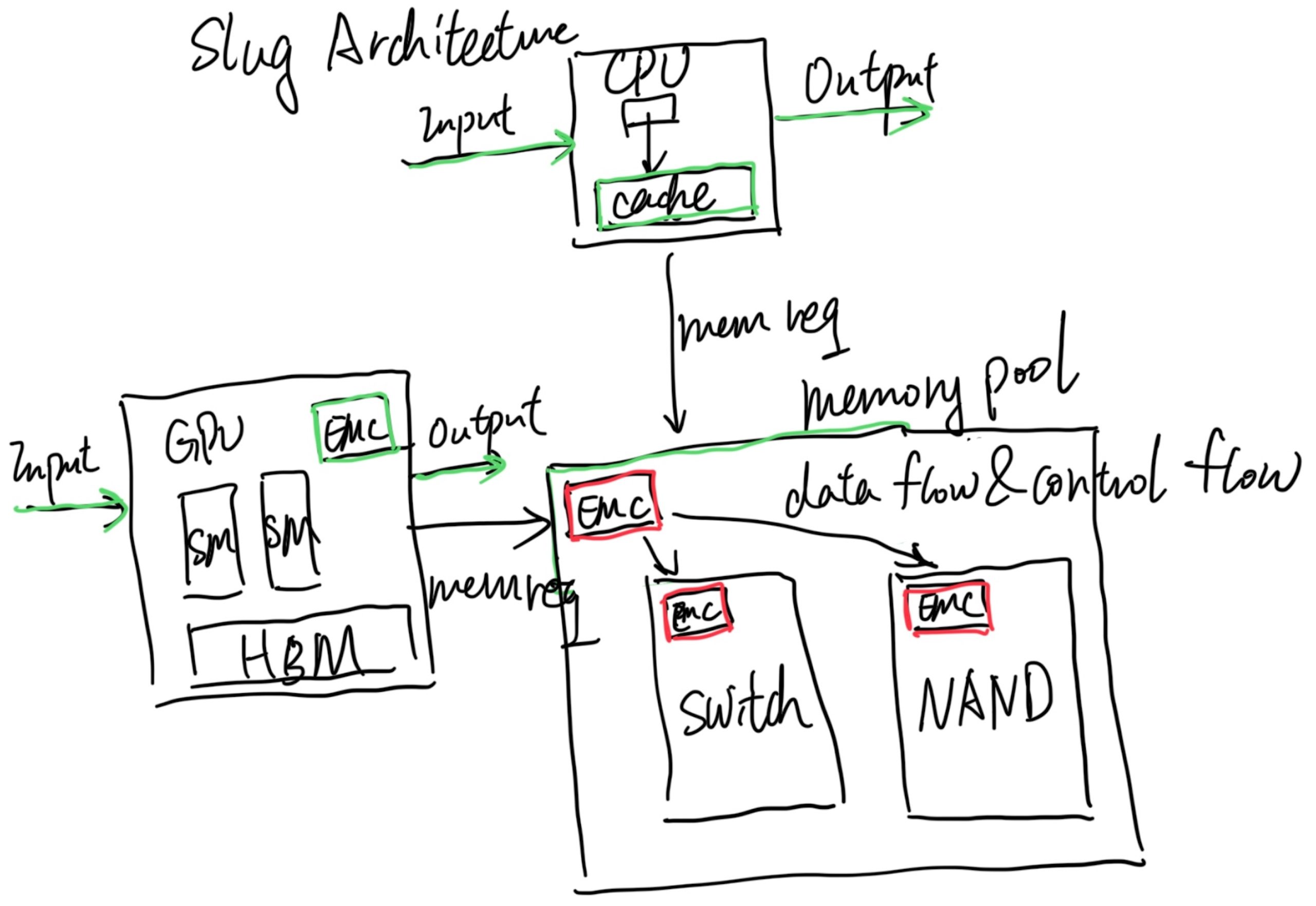
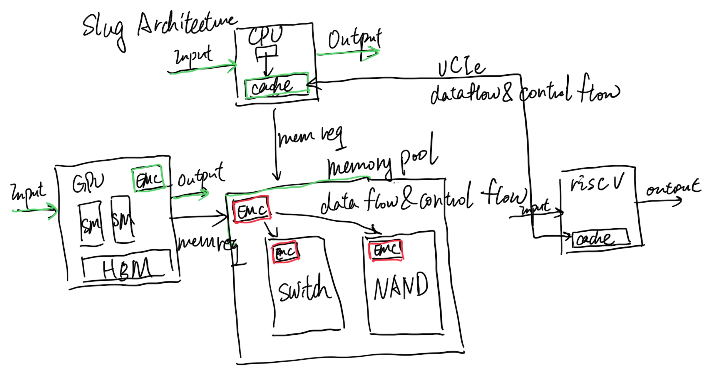
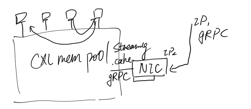
  • What kinds of resources are there, for example, CPU, memory (local vs remote that can be transparent to the user), etc.;
  • How to represent these resources with data structures;

1. resource scheduling

  • How to describe a resource application (spec) of a workload, for example, "This container requires 4 cores and 12GB~16GB(4GB local/ 8GB-12GB remote) of memory";
  • How to describe the current resource allocation status of a node, such as the amount of allocated/unallocated resources, whether it supports over-segmentation, etc.;
  • Scheduling algorithm: how to select the most suitable node for it according to the workload spec;

2.Resource quota

  • How to ensure that the amount of resources used by the workload does not exceed the preset range (so as not to affect other workloads);
  • How to ensure the quota of workload and system/basic service so that the two do not affect each other.

k8s is currently the most popular container orchestration system, so how does it solve these problems?

k8s resource model

Compared with the above questions, let's see how k8s is designed:

  1. Resource model :
    • Abstract resource types such as cpu/memory/device/hugepage;
    • Abstract the concept of node;
  2. Resource Scheduling :
    • requestThe two concepts of and are abstracted limit, respectively representing the minimum (request) and maximum (limit) resources required by a container;
    • AllocatableThe scheduling algorithm selects the appropriate node for the container according to the amount of resources currently available for allocation ( ) of each node ; Note that k8s scheduling only looks at requests, not limits .
  3. Resource enforcement :
    • Use cgroups to ensure that the maximum amount of resources used by a workload does not exceed the specified limits at multiple levels.

An example of a resource application (container):

apiVersion: v2
kind: Pod
spec:
  containers:
  - name: busybox
    image: busybox
    resources:
      limits:
        cpu: 500m
        memory: "400Mi"
      requests:
        cpu: 250m
        memory: "300Mi"
    command: ["md5sum"]
    args: ["/dev/urandom"]

Here requestsand limits represent the minimum and maximum values ​​of required resources, respectively.

  • The unit of CPU resources m is millicores the abbreviation, which means one-thousandth of a core, so cpu: 500m means that 0.5 a core is required;
  • The unit of memory is well understood, that is, common units such as MB and GB.

Node resource abstraction

$ k describe node <node>
...
Capacity:
  cpu:                          48
  mem-hard-eviction-threshold:  500Mi
  mem-soft-eviction-threshold:  1536Mi
  memory:                       263192560Ki
  pods:                         256
Allocatable:
  cpu:                 46
  memory:              258486256Ki
  pods:                256
Allocated resources:
  (Total limits may be over 100 percent, i.e., overcommitted.)
  Resource            Requests     Limits
  --------            --------     ------
  cpu                 800m (1%)    7200m (15%)
  memory              1000Mi (0%)  7324Mi (2%)
  hugepages-1Gi       0 (0%)       0 (0%)
...

Let's look at these parts separately.

Capacity

The total resources of this node (which can be simply understood as physical configuration ), for example, the above output shows that this node has 48CPU, 256GB memory, and so on.

Allocatable

The total amount of resources that can be allocated by k8s , obviously, Allocatable will not exceed Capacity, for example, there are 2 less CPUs as seen above, and only 46 are left.

Allocated

The amount of resources that this node has allocated so far, note that the message also said that the node may be oversubscribed , so the sum may exceed Allocatable, but it will not exceed Capacity.

Allocatable does not exceed Capacity, and this concept is also well understood; but which resources are allocated specifically , causing Allocatable < Capacityit?

Node resource segmentation (reserved)

Because k8s-related basic services such as kubelet/docker/containerd and other operating system processes such as systemd/journald run on each node, not all resources of a node can be used to create pods for k8s. Therefore, when k8s manages and schedules resources, it needs to separate out the resource usage and enforcement of these basic services.

To this end, k8s proposed the Node Allocatable Resources[1] proposal, from which the above terms such as Capacity and Allocatable come from. A few notes:

  • If Allocatable is available, the scheduler will use Allocatable, otherwise it will use Capacity;
  • Using Allocatable is not overcommit, using Capacity is overcommit;

Calculation formula: [Allocatable] = [NodeCapacity] - [KubeReserved] - [SystemReserved] - [HardEvictionThreshold]

Let’s look at these types separately.

System Reserved

Basic services of the operating system, such as systemd, journald, etc., are outside k8s management . k8s cannot manage the allocation of these resources, but it can manage the enforcement of these resources, as we will see later.

Kube Reserved

k8s infrastructure services, including kubelet/docker/containerd, etc. Similar to the system services above, k8s cannot manage the allocation of these resources, but it can manage the enforcement of these resources, as we will see later.

EvictionThreshold (eviction threshold)

When resources such as node memory/disk are about to be exhausted, kubelet starts to expel pods according to the QoS priority (best effort/burstable/guaranteed) , and eviction resources are reserved for this purpose.

Allocatable

Resources available for k8s to create pods.

The above is the basic resource model of k8s. Let's look at a few related configuration parameters.

Kubelet related configuration parameters

kubelet command parameters related to resource reservation (segmentation):

  • --system-reserved=""
  • --kube-reserved=""
  • --qos-reserved=""
  • --reserved-cpus=""

It can also be configured via the kubelet, for example,

$ cat /etc/kubernetes/kubelet/config
...
systemReserved:
  cpu: "2"  
  memory: "4Gi"

Do you need to use a dedicated cgroup for resource quotas for these reserved resources to ensure that they do not affect each other:

  • --kube-reserved-cgroup=""
  • --system-reserved-cgroup=""

The default is not enabled. In fact, it is difficult to achieve complete isolation. The consequence is that the system process and the pod process may affect each other. For example, as of v1.26, k8s does not support IO isolation, so the IO of the host process (such as log rotate) soars, or when a pod process executes java dump, It will affect all pods on this node.

The k8s resource model will be introduced here first, and then enter the focus of this article, how k8s uses cgroups to limit the resource usage of workloads such as containers, pods, and basic services (enforcement).

k8s cgroup design

cgroup base

groups are Linux kernel infrastructures that can limit, record and isolate the amount of resources (CPU, memory, IO, etc.) used by process groups.

There are two versions of cgroup, v1 and v2. For the difference between the two, please refer to Control Group v2. Since it's already 2023, we focus on v2. The cgroup v1 exposes more memory stats like swapiness, and all the control is flat control, v2 exposes only cpuset and memory and exposes the hierarchy view.

$ mount | grep cgroup
cgroup2 on /sys/fs/cgroup type cgroup2 (rw,nosuid,nodev,noexec,relatime,nsdelegate,memory_recursiveprot)

$ root@banana:~/CXLMemSim/microbench# ls /sys/fs/cgroup
cgroup.controllers      cpuset.mems.effective  memory.reclaim
cgroup.max.depth        dev-hugepages.mount    memory.stat
cgroup.max.descendants  dev-mqueue.mount       misc.capacity
cgroup.pressure         init.scope             misc.current
cgroup.procs            io.cost.model          sys-fs-fuse-connections.mount
cgroup.stat             io.cost.qos            sys-kernel-config.mount
cgroup.subtree_control  io.pressure            sys-kernel-debug.mount
cgroup.threads          io.prio.class          sys-kernel-tracing.mount
cpu.pressure            io.stat                system.slice
cpu.stat                memory.numa_stat       user.slice
cpuset.cpus.effective   memory.pressure        yyw

$ root@banana:~/CXLMemSim/microbench# ls /sys/fs/cgroup/yyw
cgroup.controllers      cpu.uclamp.max       memory.oom.group
cgroup.events           cpu.uclamp.min       memory.peak
cgroup.freeze           cpu.weight           memory.pressure
cgroup.kill             cpu.weight.nice      memory.reclaim
cgroup.max.depth        io.pressure          memory.stat
cgroup.max.descendants  memory.current       memory.swap.current
cgroup.pressure         memory.events        memory.swap.events
cgroup.procs            memory.events.local  memory.swap.high
cgroup.stat             memory.high          memory.swap.max
cgroup.subtree_control  memory.low           memory.swap.peak
cgroup.threads          memory.max           memory.zswap.current
cgroup.type             memory.min           memory.zswap.max
cpu.idle                memory.node_limit1   pids.current
cpu.max                 memory.node_limit2   pids.events
cpu.max.burst           memory.node_limit3   pids.max
cpu.pressure            memory.node_limit4   pids.peak
cpu.stat                memory.numa_stat

The procfs is registered in